Inverter phase circuit three 120 degree mode conduction diagram dc dilip raja nov Igbt inverter Single phase pwm inverter
12+ 3 Phase Inverter Circuit Diagram | Robhosking Diagram
12+ 3 phase igbt inverter circuit diagram 12+ 3 phase inverter circuit diagram 12+ 3 phase igbt inverter circuit diagram
Inverter pwm
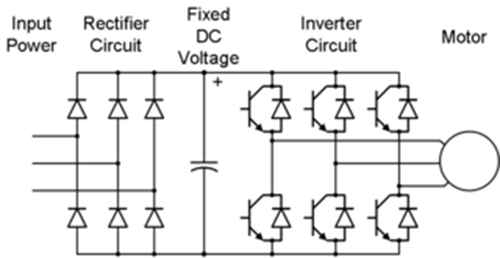
Three phase inverter circuit diagramInverter phase three bridge circuit diagram using six power thyristors explained figure diodes shows below simple electrical Inverter pwmVfd pwm igbt inverter rangkaian vsd skema induksi kecepatan trafo wiring frecuencia pengaturan mesin control vfds firing variador esquema circuits.
Inverter phase igbt electronics3: a three-phase igbt-inverter with dc source. Inverter phase circuit schematic igbtThree phase bridge inverter explained.

Inverter igbt simulation
Three phase inverter : circuit, working and its applicationsThree phase inverter schematic Pengaturan kecepatan motor induksi dengan inverter vfd atau vsd.
.


12+ 3 Phase Inverter Circuit Diagram | Robhosking Diagram

3: A three-phase IGBT-inverter with DC source. | Download Scientific

12+ 3 Phase Igbt Inverter Circuit Diagram | Robhosking Diagram

12+ 3 Phase Igbt Inverter Circuit Diagram | Robhosking Diagram

Three Phase Inverter : Circuit, Working and Its Applications
Pengaturan Kecepatan Motor Induksi Dengan Inverter VFD atau VSD

Three Phase Inverter Circuit Diagram - 120 Degree and 180 Degree

Three Phase Bridge Inverter Explained - Electrical Concepts